Quick Guide: Guide bearings and guide profiles by ALFATEC
Guide bearings and guide profiles form a linear guidance system for material handling. The bearings transfer forces to the profile’s running surfaces, while the profile defines the path of travel. Together, they guide components as they move horizontally or lift vertically. The load the system can carry depends on the components selected and how they are installed.
This technical guide explains ALFATEC part numbers, how to interpret load capacity and speed comparisons, and the information needed to select a bearing guidance system.
How do guide bearings and profiles work together?
Whether a load travels horizontally or is guided vertically, the bearing, profile and mounting must suit both the load and the installation. Each component has a distinct role.

Guide bearings and combined bearings
A guide bearing guides a moving component along a defined path. A combined bearing brings radial and axial guidance together in one assembly. Its radial bearing carries forces perpendicular to the main bearing axis. The axial bearing provides lateral guidance and carries forces along that axis.
The forces that arise depend on the guidance arrangement and the position of the load. Our combined bearing wiki article explains the principles and available designs.
Select the bearing and profile together
Loads are transferred through the contact surfaces between bearing and profile. A bearing’s load capacity alone is therefore not enough to select it. Profile geometry, running surfaces and mounting must also suit the application.
Guide clearance must suit the application too. This is the amount of play between bearing and profile perpendicular to the intended direction of travel. Matching nominal sizes alone do not confirm that two components are compatible.
Bearing design and profile shapes explained
Bearing design and profile shape affect how a guidance system can be loaded, adjusted and installed. The following distinctions help when reading technical documentation.
The components of a guide bearing
Depending on its design, a guide bearing includes an outer ring, inner ring, rolling elements, mounting stud and seals. The outer ring runs against the profile. The rolling elements allow rotation, while the stud connects the bearing to the structure.
Material, hardness, sealing and lubrication depend on the specific design. Specifications for a standard bearing do not automatically apply to stainless steel, high-temperature or polymer bearings.
U-profiles and I-profiles

U-profiles provide guidance on one side. Their cross-section has an open channel.
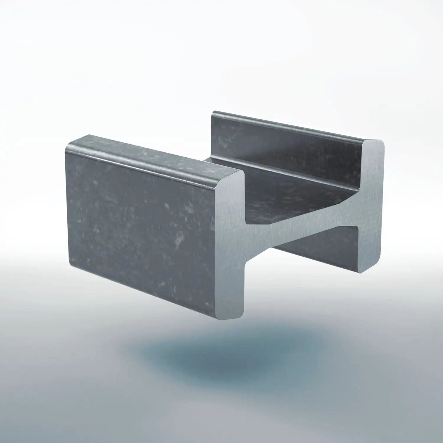
I-profiles provide guidance on both sides. Bearings can be positioned on either side of the central web.
The choice of profile depends on factors such as available space, bearing positions and how forces enter the structure. The cross-sectional shape alone does not establish a compatible bearing and profile combination.
Standard profiles and specialist designs
Guide profiles differ in how they are manufactured and machined, as well as in their cross-sectional shape:
- Standard profiles are available with a sandblasted finish, which replaces the previously offered mill-finish U- and I-profiles.
- Precision profiles have machined running surfaces for more accurate guidance.
- Stainless steel profiles are an option where corrosion resistance is required.
- Mammoth profiles are welded from several sections and then machined.
- Xtra-Strong profiles are designed for higher load capacity within the corresponding guidance system.
Profiles can be supplied cut to length and machined to suit the application. See Guide profiles for available dimensions and designs.

How do ALFATEC part numbers work?
The part number identifies the type, nominal size and design. A bearing part number may also specify a mounting element. Use the complete part number when making an enquiry.
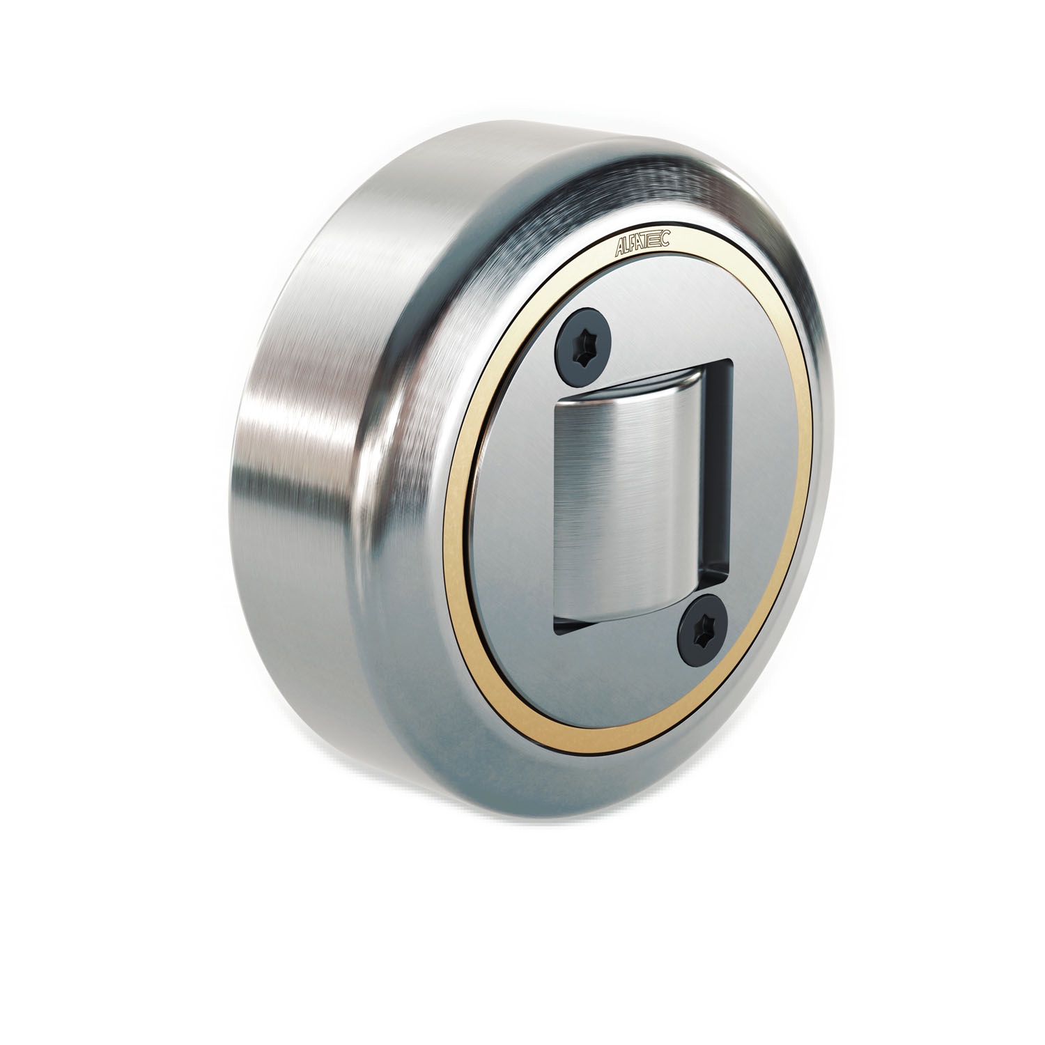
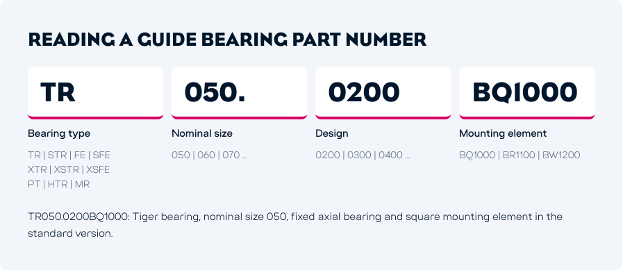
Guide bearings: TR050.0200BQ1000
- TR: Tiger bearing
- 050: Nominal size
- 0200: Fixed axial bearing
- BQ1000: Square mounting element, standard version
TR050.0200 identifies the bearing. The suffix BQ1000 specifies the version supplied with a mounting element.
Nominal size and actual diameter
The nominal size identifies a size within a series; it is not the exact bearing diameter. For example, the TR050.0200 product page gives an outer diameter of 52.5 mm for nominal size 050.
Use the dimensions of the specific design to check installation space and fit.

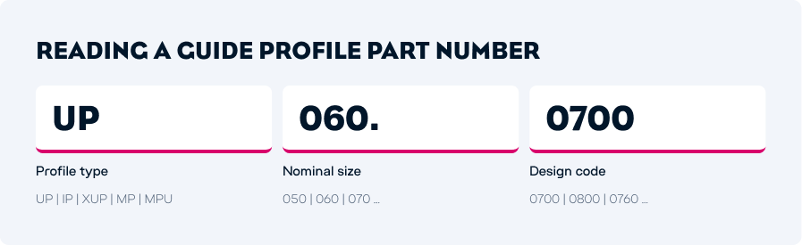
Guide profiles: UP060.0700
- UP: U-profile
- 060: Nominal size
- 0700: Design code
UP060.0700 is an example from the existing Part number structure document. It illustrates the numbering system and does not indicate a pairing with the Tiger bearing described above.
Mill-finish standard U-profiles with design code 0700 are no longer offered. They have been replaced by sandblasted versions with code 0702. Always use the currently available part number when ordering.
Mounting and spacer elements

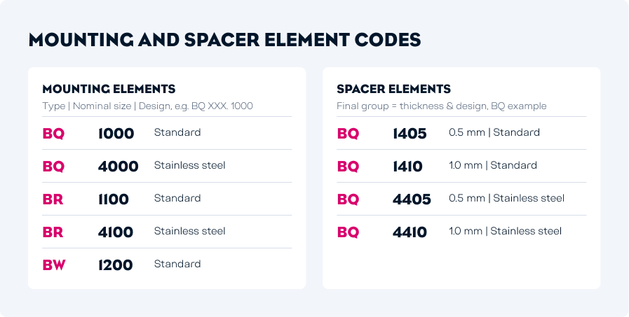
Mounting elements supplied separately also have part numbers identifying their type, nominal size and design. For BQ elements, for example, the document distinguishes between standard version 1000 and stainless steel version 4000.
For spacer elements, the final number group also indicates thickness. For BQ spacers, 1405 means a standard 0.5 mm spacer and 1410 means a standard 1.0 mm spacer. These codes apply to that element group and must not be assumed to mean the same thing for other parts.
Understanding load capacity and speed
Load and speed help narrow down the bearing families suited to an application. Selecting a specific bearing then requires a check of its individual ratings and operating conditions.
Comparing bearing families
- ALFA-Speed AS: Vulkollan running surface for dynamic motion and low rolling resistance
- ALFA-Speed PAS: Polyamide version for dynamic applications
- Tiger bearings TR: Steel bearings in a range of designs for load-bearing guidance systems
- Xtra-Strong: Higher load capacity with the corresponding guide profiles
- Mammoth bearings MR: Heavy-duty guidance with project-specific Mammoth profiles
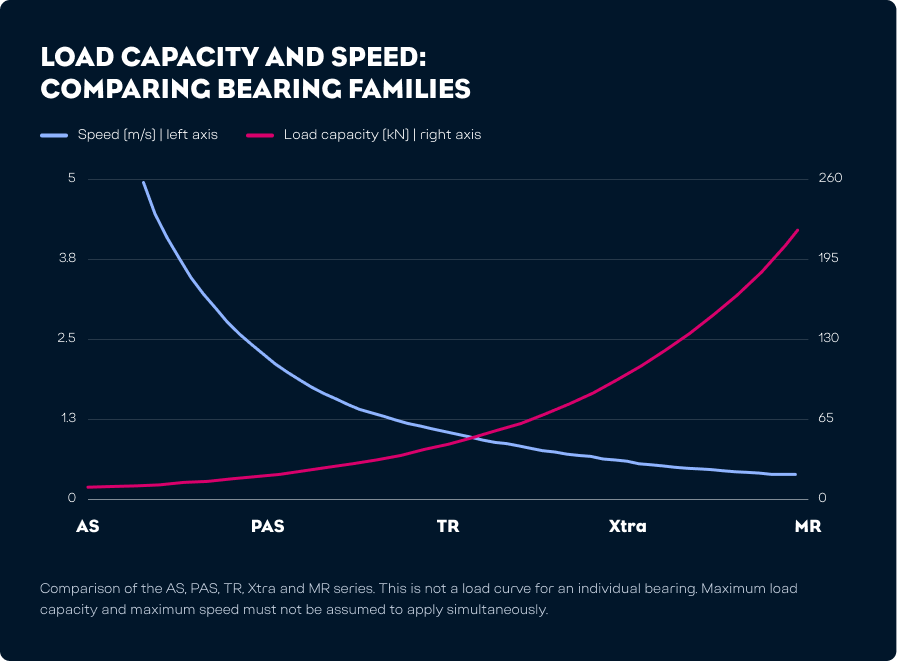
This overview covers the families shown in the load capacity and speed comparison. Other designs are available for specialist requirements, including stainless steel guide bearings. Their suitability also depends on operating and cleaning conditions.
The permissible combination of load and speed must be established for the specific bearing and its matching profile.

What does the load capacity and speed chart show?
ALFATEC’s Load capacity and speed document compares the AS, PAS, TR, Xtra and MR bearing families. Speed in m/s and load capacity in kN are shown on separate axes.
The chart compares product series. It is not a load curve for an individual bearing. It cannot be used to derive a universal calculation formula or to assume that maximum load capacity and maximum speed are available simultaneously.
Bearing load capacity and system capacity
The capacity of a single bearing is not the capacity of the complete system. The load’s centre of gravity and the spacing between bearings affect the forces acting on each bearing.
Do not assume that the total load is shared equally between all bearings. For an initial assessment, the load capacity calculator takes account of the load including dead weight, its centre of gravity and the bearing spacing.
Understanding engineering data
Read a sizing table one row at a time. The part number, dimensions and load ratings must all refer to the same design. Applying those values also requires the matching profile and relevant operating conditions.
What information must accompany a load rating?
A load rating only makes sense in context. When reading a data sheet, consider the following information together:
- Part and design: the complete bearing part number.
- Dimensions: the actual outer diameter and mounting dimensions in mm.
- Load direction: the radial or axial force in kN.
- Guide profile: the profile part number confirmed for this design.
- Operating conditions: the conditions under which the rating applies, including the intended motion.
- Source: the relevant, current data sheet.
What do Fᵣ and Fₐ mean?
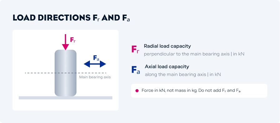
Fᵣ (FR) denotes radial load capacity, perpendicular to the main bearing axis. Fₐ (FA) denotes axial load capacity, along that axis. Both express force in kilonewtons (kN), not mass in kilograms (kg).
The values refer to different load directions. They must not be added to give a total capacity or read directly as the permissible weight of the system. Within a series, axial capacity does not necessarily increase in the same proportion as radial capacity.
Contact stress between bearing and profile
The values in ALFATEC’s engineering data sheet are based on Hertzian contact pressure between bearing and profile: the local stress at their contact surface. The profile must therefore be included when assessing load capacity.
ALFATEC must confirm the safety factors and operating limits for the specific design and application. Rotational speed in min⁻¹ and travel speed in m/s are different quantities.
Check profile compatibility and document revisions
A load rating applies to a particular bearing and profile combination. Check the complete part numbers and the corresponding drawings. Similar part numbers or matching nominal sizes are not proof of compatibility.
Use bearing and profile data from a consistent, current set of documents when sizing the system. Any design-specific conditions must be stated alongside the values they apply to.
What information is needed to select a system?
A clear description of the application makes it easier to select the right bearing and profile. A sketch showing the centre of gravity, bearing positions and mounting points helps with the assessment.
Describe the load and installation
For an initial selection, provide:
- The load, including the dead weight of all moving parts
- The position of the centre of gravity and any changes during movement
- The number, positions and spacing of the bearings
- Whether the guidance system is horizontal or vertical
- The available installation space and proposed mounting arrangement
The ALFATEC load capacity calculator uses the load including dead weight in kg, and centre-of-gravity position and bearing spacing in mm. It distinguishes between horizontal and vertical arrangements. The calculation provides an initial assessment; it does not replace approval of the specific design.
Account for motion and operating conditions
Specify speed, acceleration and how often the system moves. Permissible guide clearance, adjustment requirements and positioning accuracy also influence component selection.
Temperature, moisture, dirt and exposure to chemicals may call for specialist designs. The actual operating conditions and the properties of the selected components determine what is suitable.
What matters for installation and maintenance?
Installation orientation depends on the bearing design, the direction of the forces and the drawing of the proposed guidance system. There is no single orientation that applies to all guide bearings. Plan mounting and access to components during the design stage.
Sealing, relubrication options and care of the running surfaces depend on the specific design. Follow the relevant installation and lubrication instructions. Maintenance planning must account for load, travel and operating environment; no single lubrication interval applies to every bearing.
Products and expert advice
Once the technical requirements are clear, the product pages provide details of the available designs and their specifications.
Choose bearings, profiles and accessories
Explore the individual series under Guide bearings and Guide profiles. The modular system also includes mounting elements, clamping brackets and spacer elements.
ALFATEC also supplies bearings welded to mounting elements as ready-to-install assemblies, and components made to customer specifications and drawings. Technical descriptions and product overviews are available in the Downloads section.
Discuss your application
Planning a bearing guidance system? Send us your load data, motion requirements and a sketch of the installation. We can then review suitable bearings and profiles with you.